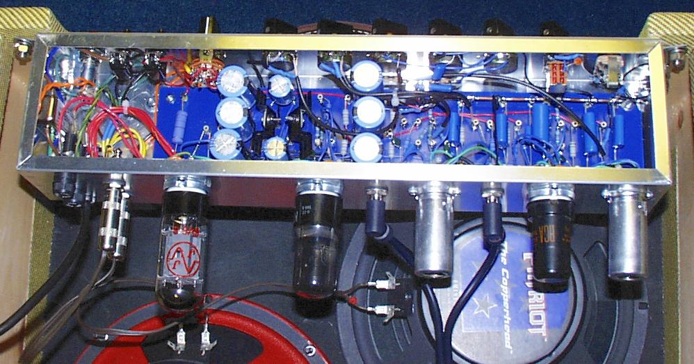
From left to right, you see the power supply, output stage, reverb driver, reverb recovery and mixer, and preamp stages. The device mounted on the left wall of the chassis is an EMI filter.
As you can see, this build was a very tight fit in the 17" x 4" x 3" chassis! I assembled the turret board outside the chassis. To install it, I had to dismount the speaker selector switch, the input jack, and the gain control. The 3" depth of the chassis allowed me to use radial electrolytics mounted vertically on the turret board. I had to lay out the board carefully to avoid collisions between the capacitors and the controls.
The grounding scheme is a hybrid star/bus ground system. The output stage and the reverb driver each have their own star ground. The other stages use a bus ground made from a length of 10 gauge solid copper wire. You can see the bus running along the top edge of the turret board on the right side. I took the chassis ground from rightmost end of the ground bus, where the cathode resistor and capacitor of the first preamp stage connect. This is contrary to what many builders do, but it was recommended in the RCA Receiving Tube Manual and it makes sense to me. I'm really pleased with the way this grounding scheme worked out. The amp is whisper quiet, with no audible hum.