Trainwreck Express Clone Oscilloscope Photos
Here are some oscilloscope photos from a Trainwreck Express
clone that I built.
The amp uses the A1A schematic from "wreckxpr.pdf"
(Google it)
with the following modifications:
- The bass pot is 1M instead of 250K.
- The first preamp stage uses two triodes in parallel, with a
50K plate resistor, 750 ohm cathode resistor, and 47uF cathode
bypass. This gives the same gain and frequency response as the
original circuit, but lowers the hiss slightly.
- The bias supply for the power stage is slightly different.
I used a Hammond 272JX power transformer and a Weber WOT45LHR
output transformer.
The amp sounds fantastic.
It does everything a Trainwreck is supposed to do.
For these photos, the amp was loaded with JJ EL34 power tubes.
The output was connected to a 4 ohm non-inductive load.
The input was driven by a 400 Hz. sine wave.
The controls were set as follows:
- Gain at 100%
- Bass, Middle, and Treble at 50%
- Presence at 0%
Amplifier Output and Preamp Stage 3 Output
In the photos below, the top trace is the speaker output of the
amp.
The bottom trace is the plate of the third preamp stage, the so-called
"cold clipper."
I adjusted the scope settings to fit both traces into each photo.
Don't try to compare the amplitudes of traces in different photos.
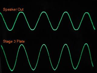
Fig. 1. Onset of clipping.
The output of the amp is just beginning to clip.
It is putting out a very clean 45 watts RMS.
The 3rd stage output is clean.
|
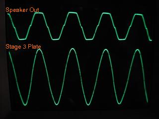
Fig. 2. Harder clipping.
With more input signal, the output clips harder.
The 3rd stage output becomes just slightly compressed on the
positive peaks.
Some crossover distortion becomes visible at the speaker
output.
As the input increases further, we'll see the crossover distortion
increase.
However, it never becomes noticeable in the sound of the amp.
|
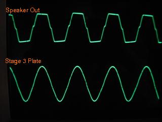
Fig. 3. Still harder.
The amp is clipping hard now in a fairly symmetric fashion.
The 3rd stage output is still quite clean, though its positive
peaks are a bit compressed.
|
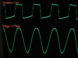
Fig. 4. Onset of 3rd stage clipping.
In this photo, the 3rd stage is significantly compressed on
its positive peaks, though it is still nicely rounded.
The speaker output is almost a square wave.
Notice, though, that the duty cycle of the waveform is no
longer 50%.
The negative excursions are quite a bit wider than the
positive excursions.
|
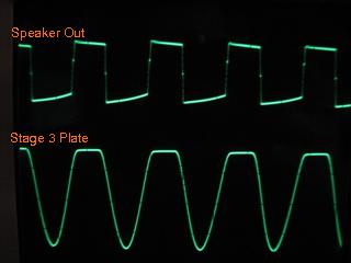
Fig. 5. Full 3rd stage clipping.
Here we are driving the amp hard enough to push the 3rd preamp
stage fully into cutoff on the positive peaks at its plate.
The output is not much different from the previous photo,
except that the rise and fall times are shorter.
|
Preamp Stage 3 Output and Preamp Stage 2 Output
In the next set of photos, the top trace is the plate of the
third preamp stage, and the bottom trace is the plate of the
second preamp stage.
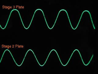
Fig. 6. Onset of 3rd stage clipping.
The positive peaks of the 3rd stage are significantly compressed,
but still rounded.
The output of the 2nd stage is undistorted.
|
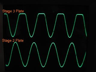
Fig. 7. Full 3rd stage clipping.
With more input signal, the 3rd stage output clips harder on
the positive peaks.
The output of the 2nd stage is still clean.
|
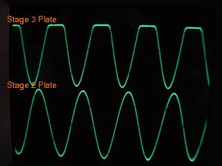
Fig. 8. Harder 3rd stage clipping.
The output of the 2nd stage is still undistorted, while the
3rd stage is clipping hard on the positive peaks.
|
Amplifier Output and Phase Inverter Output
In the next set of photos, the top trace is the speaker output of the
amp.
The bottom trace is the plate of the phase inverter on the side
with the 100k plate resistor.
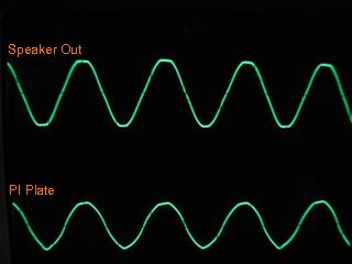
Fig. 9. Onset of clipping.
The output of the amp is just beginning to clip.
The phase inverter output is distorted strangely, somewhat
compressed on the top and a bit pointy on the bottom.
That is caused by the negative feedback around the PI and
output stage.
It is compensating for distortion in the output by
introducing counteracting distortion in the PI.
|
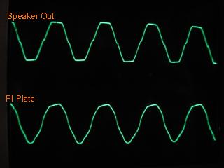
Fig. 10. Moderate clipping.
With more input signal, the output clips harder.
The PI output becomes more pointy on the bottom and more
flattened on the top, due to the negative feedback.
|
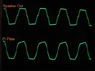
Fig. 11. Hard clipping.
Here the PI output is clipping on both peaks.
It resembles the amplifier output more closely when driven
this hard, as the ability of the negative feedback to
linearize the stages becomes exhausted.
|
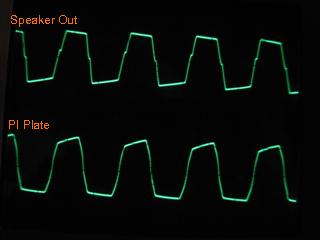
Fig. 12. Harder clipping.
More of what we saw in the previous photo.
|
Copyright © 2007-2008 John D. Polstra. All rights reserved.