On impulse, I recently modified this amp to use a push-pull output stage. The schematics and some of the descriptions that follow aren't updated yet. Here are the changes I made:
My friend John Seaberg kindly played the guitar for a few sound clips:
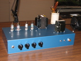
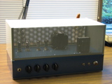
This is a little bedroom practice amp that I designed and built in the last half of 2006. The goal was a classic Marshall-style rock & roll tone in a very low-power amplifier. I wanted to be able to dime the controls without making my ears ring.
This amp puts out 2.2W undistorted, but that's misleading because no one would ever play it undistorted. When it is cranked, as it is meant to be all the time, its power tubes are strongly overdriven, and the actual power output is well above the rated value. The last time I played it, my wife rather pointedly donned a pair of hearing protection headphones. I admit I'm not one of the world's great guitar talents, but she doesn't usually cover her ears just because of that. You wouldn't want to gig with this amp, but it's plenty loud for home use.
Many flea-power guitar amps are built around a dual triode output stage, often using a 12AU7A push-pull circuit. I wanted this amp to come closer to the sound of a big amp, so I decided to use a pair of small power pentodes instead. I used two 6AK6 pentodes, rated at 2.75W plate dissipation, in a parallel single-ended configuration.
Click on any picture for a larger version with construction notes.
|
|
|
|
|
|
|
|
Since I wanted most of the distortion in this amp to come from the power tubes, I designed the preamp to be almost completely clean. Scope traces show that the output stage is ovedriven far into clipping while the preamp output is still undistorted.
The input stage uses a 6AU6A pentode. I originally based the resistor values on the resistance-coupled amplifier tables in an old RCA tube manual, but that didn't give good results. I think the table must have had errors in it, because using the given values, the plate voltage was very low -- much lower than the screen voltage, in fact. I tried several different tubes, with similar results. Although I did get some signal out of the stage, it sounded pretty nasty. I played around with the values of the plate and screen resistors, finally arriving at the values shown in the schematic. These values give me a good clean signal with about the right amount of gain for this amp.
The input stage feeds a 12AU7A cathode follower, which provides a nice low impedance drive for the tone stack without loading the pentode stage. The tone stack is a standard Marshall configuration, using the more modern "Hendrix mod" values for the slope resistor and treble capacitor rather than the values used in the earliest Marshall amps. I like the overall sound of this tone stack for rock music, but I may tweak it some more. As things stand now, the amp is a little bit too bassy for my taste.
The tone stack and gain control feed a second gain stage using the other half of the 12AU7A. This stage has relatively low gain, due to the low mu value of the 12AU7A and the unbypassed cathode resistor. I originally had a bypass capacitor on this stage, but I found that it gave me more gain than I needed.
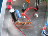
The output stage is a cathode-biased parallel single-ended stage using two 6AK6 power pentodes. The 6AK6 is a 7-pin miniature version of the 6G6 octal tube, with essentially identical specifications. Its plate dissipation rating is 2.75W, and in a typical class A stage it can deliver 1.1W into a 10K load with 10% distortion. By running two tubes in parallel, I was able to use a fine Heyboer 5K output transformer that I bought from the nice folks at Doberman Music Products. The power tubes run with 180V on the plates and screens, and 15mA plate current -- values I took directly from the data sheet.
I used separate cathode resistors and bypass capacitors for the two power tubes, for two reasons. First, with separate cathode resistors the tubes don't have to be matched as well. Each tube biases itself without affecting the bias of the other tube. When a shared cathode resistor is used, any mismatch between the tubes is magnified. If one tube is "hotter" than the other, then its extra current raises the cathode voltage and causes the other tube to run even colder than it would run on its own. Using separate cathode resistors, I found I could use any two random 6AK6 tubes without any problems.
Second, the separate cathode resistors allow me to remove V4 and run the amp on just a single power tube when I want to. This has some interesting effects. It reduces the loudness of the amp, but not as much as you might expect. It also changes the harmonic structure of the distortion, giving much more 2nd harmonic content and much less 3rd harmonic. There is a graph in the RCA data sheet for the 6AK6 showing this.
I like the single-tube option enough that I plan to make it switchable. That's easy to add. Just insert a 47K resistor in series with R16, with a switch that shorts out the new resistor when it is turned on. C10 should bypass both resistors. When the switch is closed, the circuit is identical to the schematic as drawn. When the switch is open, V4 is biased into cutoff and is effectively removed from the circuit.
The heater circuit is referenced to the cathode of V3 (about 9V), using a virtual center-tap made from two 110 ohm resistors. That is not shown in the schematic.
The power supply is conventional, and there is not much to say about it. The large dropping resistor (R18) gets the B+ voltage right and provides a lot of filtering.